
Every active sonar puts the same question to the sea: is something there, and what is it? It gets one kind of answer, an echo. Whether that echo is heard at ten kilometres or only at two depends on the sonar, on the sea, and on one quantity that belongs to the target alone: how strongly it sends sound back.
That quantity matters to two groups of engineers who rarely sit at the same table. The sonar designer needs it to predict detection range: without a figure for the echo there is no figure for range. The submarine designer needs it for the opposite reason, to know how loudly the boat answers a ping and what each design choice does to that answer. The physics is the same for both, and it does not care whether the object is a submarine, an iceberg or a whale.
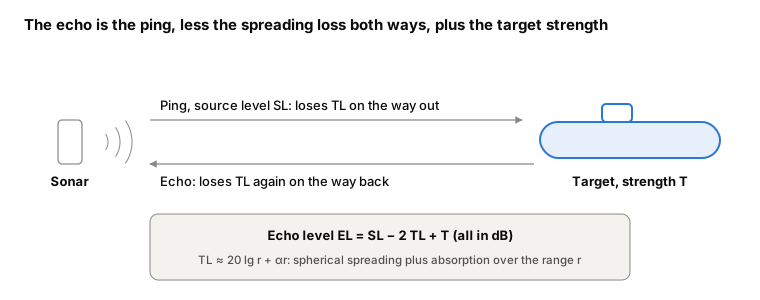
What the echo carries
An echo is not just "something came back". It carries three kinds of information:
- Amplitude: how much sound came back. This is the quantity target strength measures, and the one that decides detection range.
- Phase: the timing of the returning wave, which coherent processing uses to pull a weak echo out of noise.
- The shape of the echo envelope: a long hull does not return a single click. Seen end-on, sound from the bow and the stern of a 66 m boat comes back up to 88 milliseconds apart, so the echo is stretched in time; seen on the beam, it is short and sharp. The envelope says something about the size and aspect of what was hit.
Of all the sound a ping deposits on a hull, only the part sent back towards the sonar counts, at least for a sonar that transmits and listens from the same place. The rest is reflected and scattered in other directions and is lost to that sonar. This is the root of acoustic shaping: a surface that turns sound away is quiet to the sonar that sent it, even if it reflects strongly.
The exact problem, and why it is rarely solved in design
In principle the echo is found by solving the wave equation with the right boundary conditions on every surface the sound meets: the outer hull, the frames and tanks behind it, the pressure hull, and any coating. Full-wave numerical methods do exactly this, and they are the reference against which simpler methods are judged.
Their cost grows with the square of frequency. At 5 kHz the wavelength in water is 30 cm; meshing some 2,000 m² of outer hull at six elements per wavelength needs of the order of 800,000 elements, and at 20 kHz about sixteen times that, before the structure inside is counted. That is acceptable for a benchmark, and impractical in a design loop that has to cover hundreds of aspects, several frequencies and a dozen shaping and coating options.
Three assumptions that make it computable
The engineering approach accepts a small loss of precision in exchange for calculations that can be repeated as often as the design changes. It rests on three physical assumptions, and each of them has to be checked rather than taken for granted.
- The object is large compared with the wavelength. At 5 kHz the wavelength is 30 cm and at 20 kHz 7.5 cm, against a hull several metres across. At these sizes sound behaves much like rays: smooth surfaces reflect specularly, the echoes of simple bodies have closed-form expressions, and diffraction around edges is a small correction. The assumption weakens at low frequency. At 1 kHz the wavelength is 1.5 m against a hull radius of about 4.5 m, which is why this kind of method is used over roughly 1–20 kHz and not below.
- The water around the object is unbounded. There is no seabed and no sea surface in the calculation. This separates the target from the environment: target strength becomes a property of the target alone, and the sea's contribution (spreading, absorption, bottom and surface paths) is accounted for separately, in the propagation loss. In shallow water that separation is under strain, a subject for a later article.
- The sonar is far away compared with the size of the object. This is the easiest assumption to state and the easiest to under-check. The common rule, range much greater than the length of the target, is not enough for a long, flat-sided body. What matters is whether the body fits inside the first Fresnel zone, the stretch of hull that reflects in phase; for a body of length L at wavelength λ that requires a range greater than about L²/2λ. For a 40 m hull section at 5 kHz that is 2.7 km. Closer in, only the middle of the hull reflects in phase, and a far-field formula overstates its beam echo by about 10 dB at 1 km.
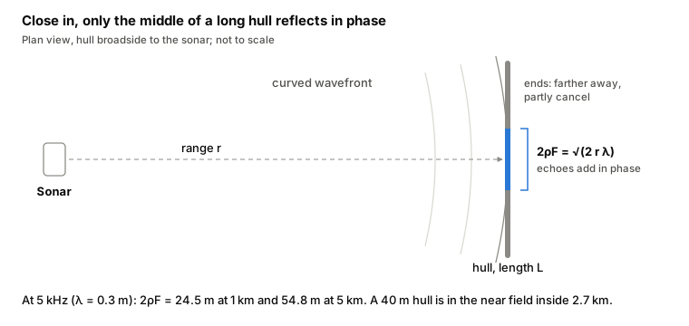
This is why SSR-Sim, the target-strength software we developed at Oravont and use in our sonar signal reflection service, tests every body at every frequency and range and uses the near-field form where the far-field assumption fails, rather than assuming it holds.
What the assumptions buy
With these three assumptions in place, a submarine can be broken down into a set of simple bodies (spheres, cylinders, cones and plates), each with a known echo, and the echo of the whole boat assembled from them aspect by aspect and frequency by frequency. How that decomposition is done, and why the phases of the parts are deliberately set aside when they are added, is the subject of the next article.
The assumptions are not weaknesses to be hidden. They are the method's terms of use. A target-strength figure is only as good as the check that its assumptions hold for the body, the frequency and the range in question.
Worked results for a generic 66 m double-hull submarine (aspect, frequency, range, hull components and coatings) are in the working note SSR-Sim: what a submarine's sonar echo is made of. Oravont estimates the target strength of submarine and surface-ship designs, shows which bodies dominate the echo, and weighs shaping and coating options before a CAD model exists: sonar signal reflection and target strength service.
About the author. Capt (Dr) Sunil Tyagi, Indian Navy (Retd), is the founder and principal of Oravont Systems LLP. For six years he headed the Acoustic Stealth Group at the Directorate of Submarine Design, Naval Headquarters. Profile, CV and publications: suniltyagi.in.