
Ping, echo and target strength
An active sonar sends a ping and listens for its echo. On the way to the target the sound spreads and is absorbed, and it loses the same again on the way back. The boat's own contribution to the echo is its target strength T: how much of the sound reaching it comes back, measured 1 m from the target.
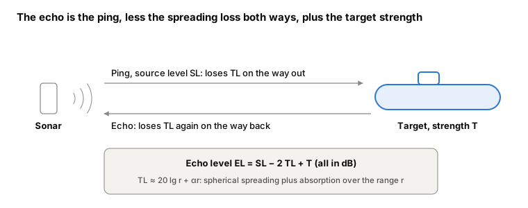
Target strength is measured against a sphere. A large rigid sphere of radius a reflects with T = 20 lg(a/2), so a sphere of radius 2 m has T = 0 dB [1]. SSR-Sim computes the boat's equivalent radius Rₑ, the radius of the sphere that would echo as strongly, and from it T = 20 lg Rₑ − 6 dB. The level 20 lg Rₑ is what earlier SSR plots show as "SSR level"; T is the same curve 6 dB lower.
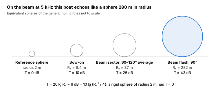
Every 20 dB is a factor of ten in equivalent radius. A sonar that just detects the boat bow-on at 10 dB would detect it on the beam flash 33 dB stronger, which is why designers care about the beam and treat the sail and hull sides first.
The method in brief
The hull and its structures are cut into simple bodies: spheres, cylinders, cones, plates. Each body's return is computed in closed form [1, 4], in three parts:
- Specular reflection from the outer surface, and from the pressure hull behind it, through the outer plating.
- Diffuse scattering from the structure between the hulls.
- Non-specular re-radiation from the stiffened shell, driven by its frames [5].
The parts are summed on an energy basis into the echo of the whole boat, at each aspect and frequency. Coatings enter as measured reflection and transmission coefficients, so the same run shows what a coating scheme buys.
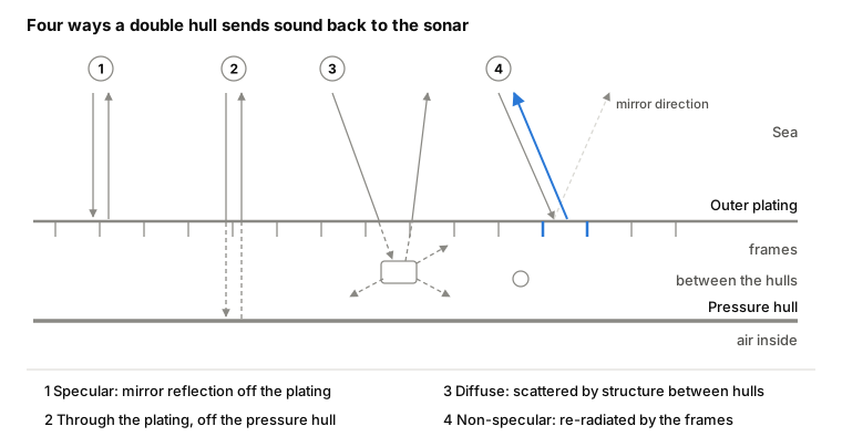
Specular reflection is mirror-like: a body returns sound strongly only where its surface faces the sonar. A straight body of length L squeezes that echo into a lobe about λ/L radians wide, which for the 40 m hull at 5 kHz (λ = 0.3 m) is 0.4°. Thin plating is also partly transparent. By the mass law [3], 8 mm of steel at 5 kHz reflects about 30% of the sound energy that strikes it and passes about 70%, so the pressure hull behind it echoes too (path 2).
Diffuse scattering comes from the frames, tanks and pipes between the hulls. It is weak against a specular flash, but it is everywhere else: more than 10° from either flash it carries 70–94% of the echo on this hull, 91% typically. It is lowest dead ahead and astern, where the domes face the sonar. Non-specular re-radiation by the framed plating stays below 3% here.
The test hull
An invented boat, not any real class: a 66 m double hull in bare steel. Result 5 adds an illustrative coating.
| Body | Shape | Main dimensions |
|---|---|---|
| Bow dome | Hemisphere | Radius 4.5 m |
| Hull cylinder | Cylinder, 60 frames | 40 m long, radius 4.5 m, 8 mm plating |
| Stern cone | Cone, 24 frames | Half-angle 12°, 21 m long |
| Pressure hull | Cylinder behind the outer hull | 38 m long, radius 3.6 m |
| Pressure-hull domes | Two hemispheres | Radius 3.6 m |
| Sail sides | Flat plates | 9 × 5 m |
| Rudder | Flat plate | 4 × 3.5 m |
All results were computed with SSR-Sim r5 in its engineering profile. Unless stated, the sonar is 5 km away, in the horizontal plane, and aspect is measured from the bow (0° bow-on, 90° beam).
Result 1: target strength against aspect
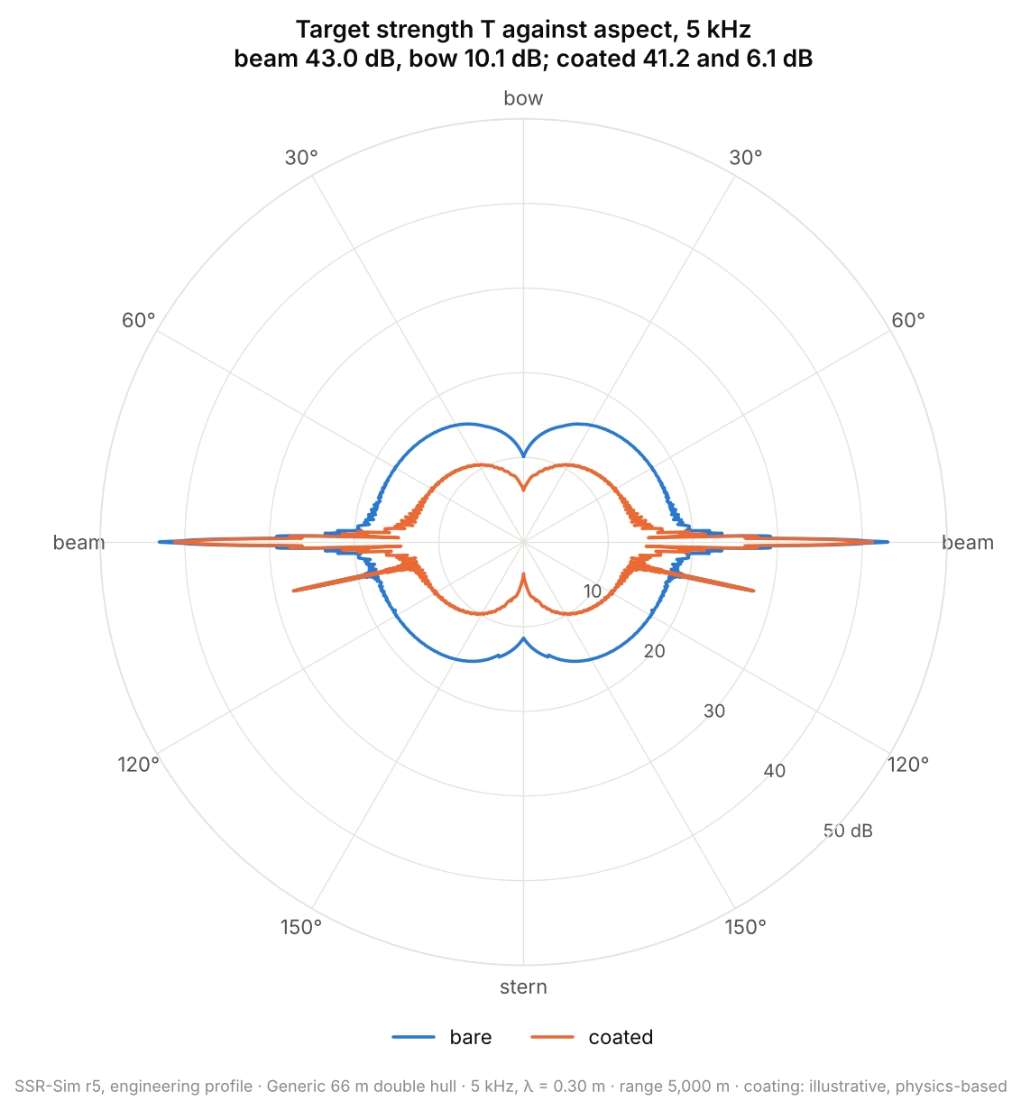
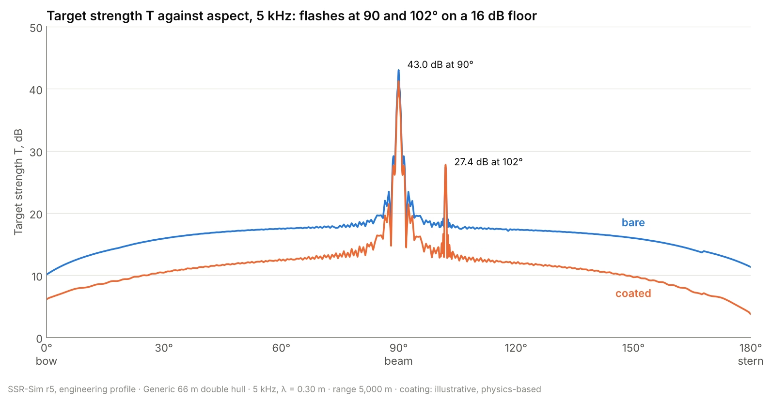
The boat is a floor of 10–20 dB with two narrow flashes: 43 dB on the beam, and 27 dB at 102°, where the flank of the stern cone faces the sonar. The beam flash is less than a degree wide. Averaged over the beam sector (60–120°) the level is 25 dB, 18 dB below the flash, and that average is what a sonar sees on a boat whose aspect it does not know. The orange curve is the same hull with an illustrative coating (Result 5).
Result 2: how it changes with frequency
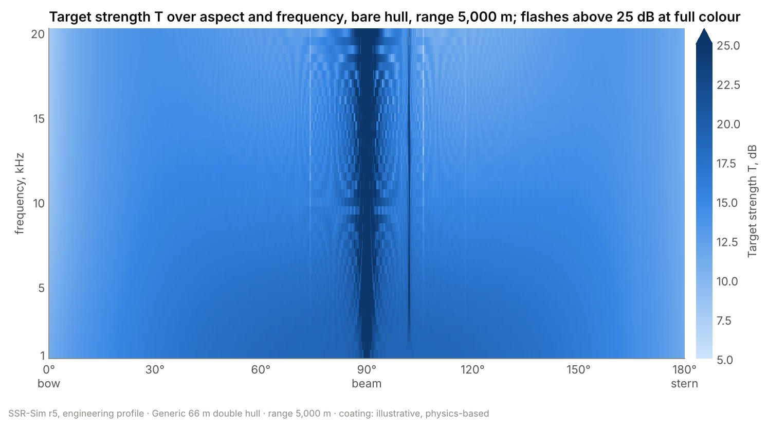
From 1 to 20 kHz the beam flash rises from 33 to 56 dB, about 5–6 dB for each doubling of frequency: a flat plate's echo rises 6 dB per doubling and a cylinder's 3 dB, and the flat sail sides dominate. The flash also narrows, since its width goes as λ/L. The floor does the opposite, falling about 4 dB over the band, because the outer plating lets less sound through as frequency rises and less reaches the structure between the hulls.
Result 3: where the echo comes from
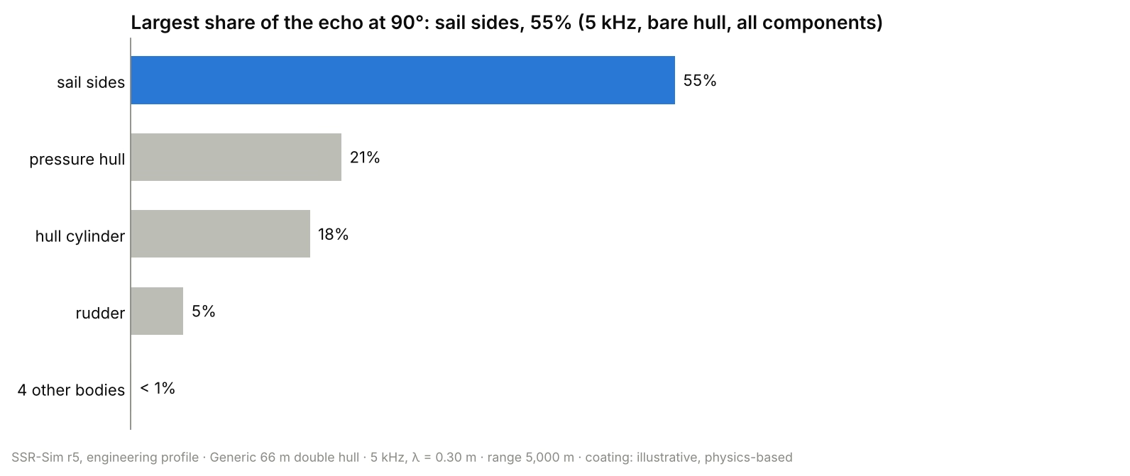
On the beam the echo is almost all specular, and the sail's flat sides, at exact normal incidence, outweigh the 40 m hull cylinder. That is the case for curving and coating a sail, made in one number. The pressure hull returns more than the outer hull in front of it: 8 mm of steel lets most of the sound through at 5 kHz.
Bow-on the picture changes. The bow dome carries 84% of a much weaker echo, and 70% of that echo is diffuse scattering from inside the double hull rather than reflection from its skin.
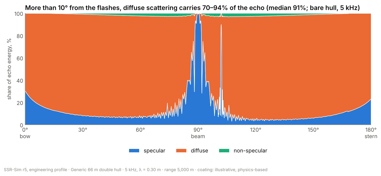
Across all aspects, the specular component owns only the flashes. Everywhere else the echo is mostly diffuse, and the frames' non-specular re-radiation never exceeds a few percent on this hull.
Result 4: what changes with range
Target strength is the echo referred to 1 m from the target, so it describes the target, not the distance. In SSR-Sim it changes with range only through the near-field test, and on this hull that touches only the beam flash. At every other aspect T is the same from 100 m to 20 km. On the beam it is 1.9 dB lower at 1 km than far away, and 8 dB lower at 100 m, where even the flat sail sides fall into their near field. (The method has no near-field form for a cone, so the 102° flash stays fixed.)
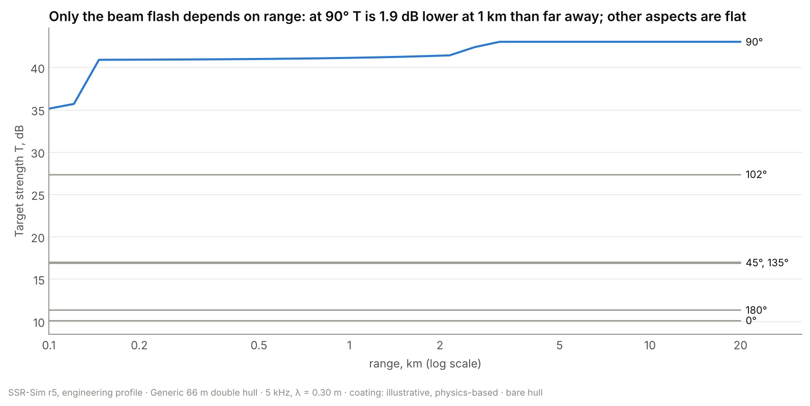
The beam flash moves because its long bodies do. Taken alone, the 40 m hull cylinder shows the effect in full:
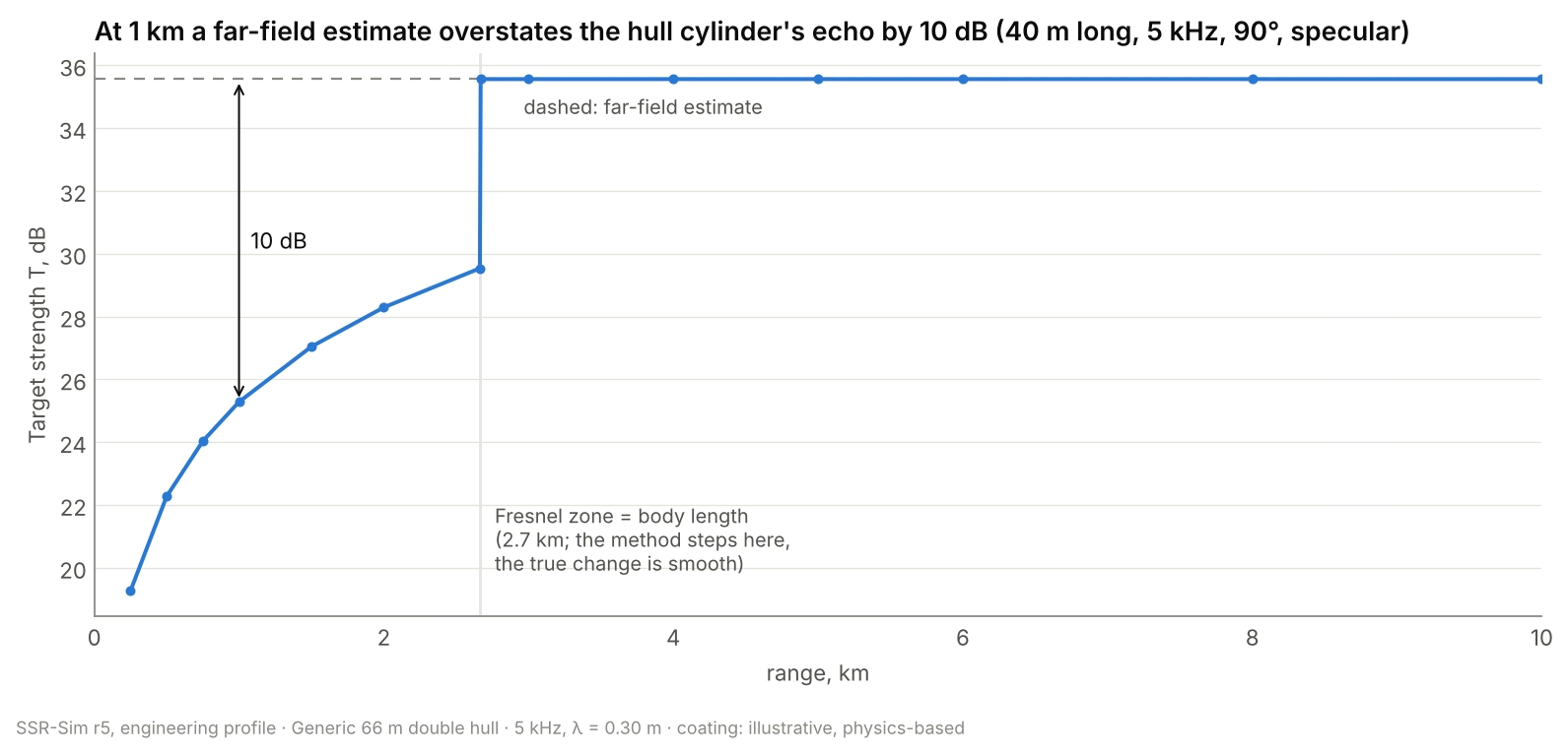
A 40 m hull is long against the sonar's Fresnel zone out to about 2.7 km at 5 kHz, and inside that range only part of its length reflects in phase. A far-field formula, the usual quick estimate, ignores this and overstates the hull's specular echo by 10 dB at 1 km and 13 dB at 500 m. SSR-Sim tests every body at every frequency and range and uses the form that applies. The effect grows with frequency and hull length, and it matters for torpedo seekers and close-range sonars.
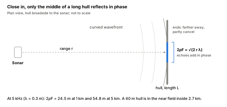
The reason is the curvature of the sonar's wavefront. Seen from range r, points on a straight hull a distance x from its middle are farther away by about x²/r on the round trip. Where that extra path exceeds half a wavelength, their echoes arrive out of step and partly cancel. The stretch that reflects in phase is the first Fresnel zone, 2ρF = √(2rλ), and a body longer than it is in the near field.
What does fall with distance is the echo that reaches the sonar. With EL = SL − 2TL + T and TL = 20 lg r + αr, the echo loses 12 dB for each doubling of range from spreading alone, and absorption (0.38 dB/km at 5 kHz, by Thorp's formula [2]) bends the curves down beyond a few kilometres. At 10 km the beam flash returns 125 dB below the source level, the beam-sector average 141 dB and the bow 158 dB.
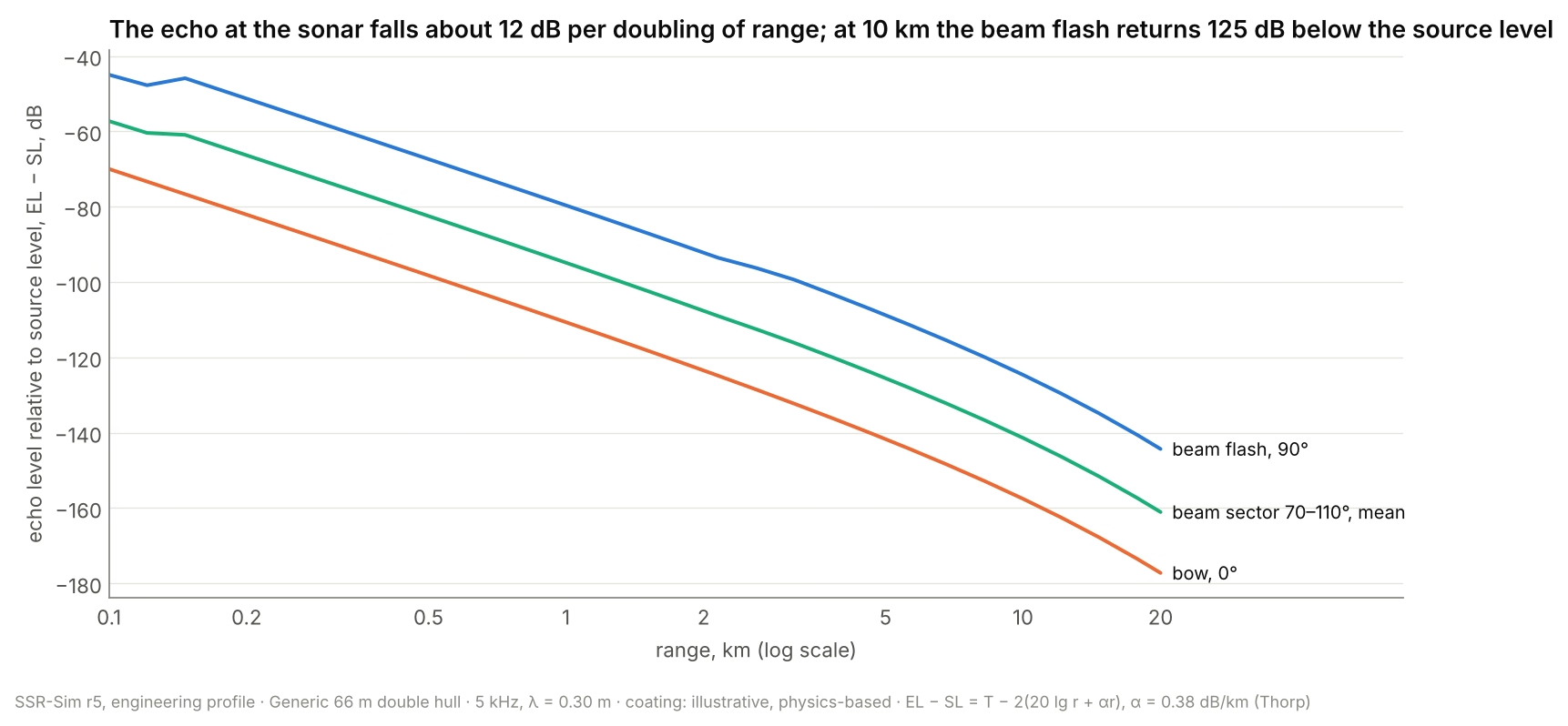
Whether that echo is detected depends on the sonar's source level, the noise and the processing: properties of the sonar, not of the target. Target strength is the target's share of that budget.
Result 5: what a coating buys
The coating here is illustrative: physics-based values, not a real product. At 5 kHz its outer face reflects 0.60 of the incident sound pressure and passes 0.16, and its inner face reflects 0.60. In energy that is 36% reflected, 3% passed and 61% absorbed, against 30% reflected and 70% passed for the bare 8 mm steel.
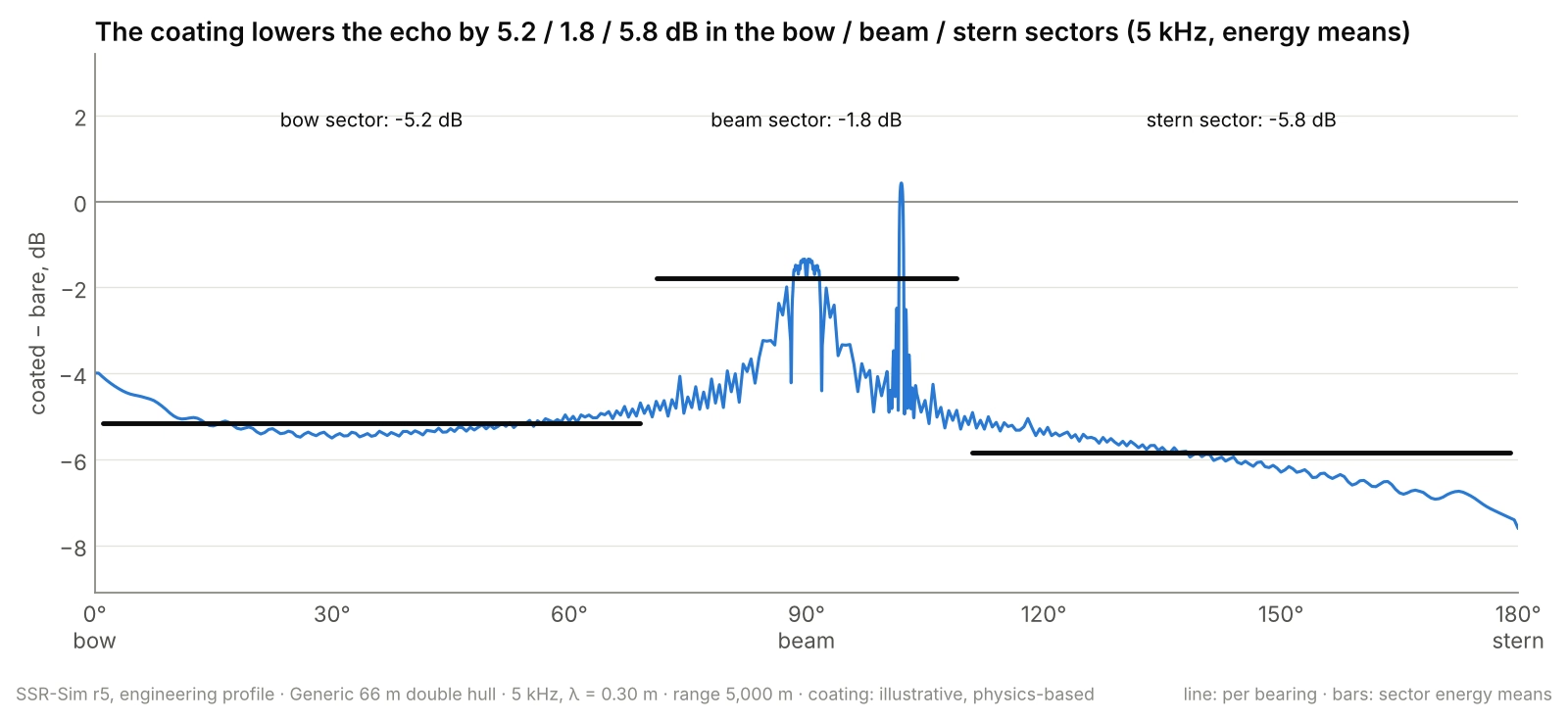
The coating lowers the echo by about 5 dB in the bow and stern sectors but only 1.8 dB on the beam. Its front face reflects as much as bare steel, so the specular flash barely moves. What it does is cut the sound passing through the outer hull from 70% to 3%, and that removes most of the diffuse floor and the pressure hull's return. Coating design is therefore a fight about transmission and absorption, not only about the front face.
Limits and what comes next
The method is a high-frequency approximation. It holds where the bodies are large against the wavelength: about 1–20 kHz for a submarine.
- Averaged, not single-ping. The energy sum gives the phase-averaged level. One ping at one aspect can swing several decibels either side of it.
- Not modelled: interaction between bodies, edge diffraction, the propeller, and appendages only a wavelength or two long.
- A stepped near-field switch. The change between short and long forms is a step, where the real transition is smooth.
- Validation so far is against the method's own worked example. A comparison with full-wave results on a public benchmark hull, such as the BeTSSi submarine [6], is next.
Also next: coating data that vary with depth and angle, and the echo's time structure from each body's position along the hull, for simulators and seeker testing.
All results here are for an invented hull and an illustrative coating, and describe the method at headline level.
References
- R. J. Urick, Principles of Underwater Sound, 3rd ed. New York: McGraw-Hill, 1983. Target strength, the sonar equation, echoes from simple shapes.
- W. H. Thorp, "Analytic description of the low-frequency attenuation coefficient," J. Acoust. Soc. Am., vol. 42, no. 1, p. 270, 1967. Sea-water absorption.
- L. E. Kinsler, A. R. Frey, A. B. Coppens and J. V. Sanders, Fundamentals of Acoustics, 4th ed. New York: Wiley, 2000. Transmission through a thin plate; the mass law.
- J. J. Bowman, T. B. A. Senior and P. L. E. Uslenghi (eds.), Electromagnetic and Acoustic Scattering by Simple Shapes. Amsterdam: North-Holland, 1969. Scattering by spheres, cylinders, cones and plates.
- M. C. Junger and D. Feit, Sound, Structures, and Their Interaction, 2nd ed. Cambridge, MA: MIT Press, 1986. Fluid-loaded plates and shells, and the effect of stiffeners.
- M. Östberg, "Target echo strength modelling at FOI, including results from the BeTSSi II workshop," arXiv:1604.02257, 2016. The BeTSSi benchmark submarine and how target-strength codes compare on it.
SSR-Sim is one of Oravont's own engineering tools, made available to defence organisations, shipyards and research institutions on enquiry. See the acoustic stealth track and Contact.